Week 10: network connections
Outline
Before you attend this week’s lab, make sure:
-
you have completed the interrupt lab and understand how signals (i.e. voltage changes) on your GPIO pins can trigger interrupts
-
you have completed the inputs lab and understand how to process signals from your GPIO pins as inputs and outputs
In this week’s lab you will:
-
configure the GPIO pins on your board for both input and output
-
connect the microbit rings to one another with physical wires
-
configure and write interrupt handlers to do things when stuff happens on these wires
-
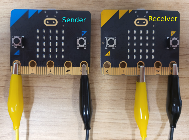
(in-person only) connect your microbit to a tutor’s microbit to demonstrate intra-microbit communication
-
simulate a multi-microbit setup where you connect the two sides of your microbit to each other with wires and send packet data across the wires turn on LEDs
Introduction
This week you’ll take a deeper dive into the GPIO & interrupt capability on your microbit to send messages from one microbit to another. As you know, the GP in GPIO stands for General Purpose, which means that each pin (the barcode-like little gold-coloured bits of metal in rows along the bottom of your microbit) can be used for either input or output. The mode (input mode, output mode) of a given pin is configured by writing certain bits to the GPIO configuration registers.
This week, you’ll extend your knowledge of GPIO inputs, timers, and interrupts from weeks 8 and 9 change the GPIO output of a pin over time to represent a message, and then to sense and decode that message on another pin.
This lab has some more gaps in the instructions, so make sure you ask your tutors if you get stuck. If you are having trouble, read the interrupt classic gotchas section where you can check off some typical problems with enabling interrupts.
Today you’ll be working on sending signals to and from GPIO pins by connecting these pins using clip wires. To start off, think about: in the context of GPIO pins, what is a signal? Is there a difference between a signal which comes internally through the microbit (e.g. the buttons on your board and the signal which comes in through an external wire?
Before you start, fork and clone the lab template
Task 1: blink-over-the-wire with polling
This first task is going to seem like revision of the interrupts lab where you used SysTick to blink an LED, however this time you will use SysTick to send a signal across a wire to toggle the LED.
The good news is that you already have all the knowledge needed to make this work from your previous weeks labs. It’s just a matter of stitching all the pieces together!
First, connect a jumper wire from Ring0 to Ring2
on your microbit, like so:
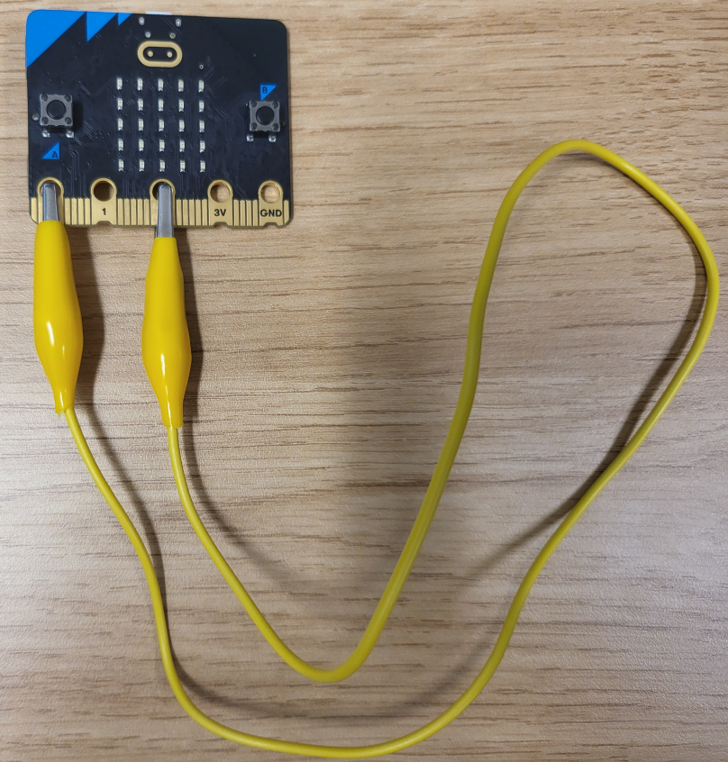
Now, using SysTick, you’re going to send a signal from Ring0 to Ring2
to turn an LED on and off. Here’s an outline of what your code should do to complete this task:
- Configure
Ring0(P0.02) as an output - Configure
Ring2(P0.04) as an input- This isn’t just setting the pin as an input, you also need to configure GPIOTE
to enable updating the
INevent for this pin. Section 6.9.4.8 of the nRF52833 Product Specification can help with this. Specifically, we want to enable the event for Pin 4 on Port 0 (but not as an interrupt… yet).
- This isn’t just setting the pin as an input, you also need to configure GPIOTE
to enable updating the
- Configure
SysTickto interrupt at a constant rate - In the
SysTickhandler you should toggle the output state ofRing0 - In the
mainloop of the program, you should poll the state ofRing2and …- Turn an LED on if the signal is high (1)
- Turn the same LED off if the signal is low (0)
All of these steps are things you have done before in previous labs, so look back through your lab tasks if you need to find hints on how to accomplish these tasks. Note that we are using a polling strategy to respond to input data from the GPIO pin.
To check your task is working correctly: Make sure that when the clip wire is connected, your LED blinks, but when it is disconnected, the blinking stops.
Write a program which blinks an LED at a rate of 2 times per second
using the jumper wire by polling.
Copy your code to task-1.S and push it to gitlab.
Task 2: blink-over-the-wire with interrupts
As discussed in lectures, polling the current value on the pin in a loop isn’t always the best way to respond to inputs because it makes it hard for your program to do other work simultaneously. Happily, there’s a better way! In this task, you’re going to configure the GPIO input pin to trigger an interrupt when the value changes.
Modify your code from task-1 so that Ring2 (P0.02) triggers an interrupt when
it detects a change on the line and sets the LED accordingly. Here’s an outline of what your program will have to do to accomplish this task:
- Configure
Ring0(P0.02) as an output - Configure
Ring2(P0.04) as an interrupt enabled input - Configure
SysTickto interrupt at a constant rate - In the
SysTickhandler you should toggle the output state ofRing0 - In the
GPIOTE_IRQHandleryou should read the state ofRing2and …- Turn an LED on if the signal is high (1)
- Turn the same LED off if the signal is low (0)
- Clear the interrupt pending bit
- Do nothing in the main loop (make sure your program loops endlessly in main)
Write a program which blinks an LED at a rate of 2 times per second
using the jumper wire with interrupts.
Copy your code to task-2.S and push it to gitlab.
Task 3: LED coordinate packet over the wire
For this task your job is to create a “sender” program that sends a packet of data to a tutor’s microbit which will have the corresponding receiver code. You will connect your microbit to a tutor’s to check that your program is working.
Remote students: Unfortunately we can’t mail a tutor to you, so unless you can meet up with someone who has a microbit you’re not going to be able to test this exercise. But don’t fret! You can just skip the testing of this step and move on to task-4 where you’ll get to write both the sender and receiver on the same microbit.
In this task we’re going to connect microbits together!
Before looking at what you have to do to create the sender program we need to establish an agreed form of communication between your microbit and the tutor’s microbit. (Drum roll…) Introducing P2300-1W! A 1 way, 1 wire, serial protocol for controlling LEDs.
P2300-1W Features:
- 1000 bits per second bit rate (1 bit per millisecond)
- Packet based serial transmission
- Each 10 bit packet consists of:
- 1 start bit
- 1 byte of data
- 1 stop bit
- Each data block consists of:
- 4 bits indicating the LED row index (most significant 4 bits)
- 4 bits indicating the LED column index (least significant 4 bits)
- Data is transmitted in big endian (most significant bit first)
- Default high signal (line stays at 1 when no data is being transmitted)
So now that you understand the protocol, here’s an outline of what your code will need to do to complete this task:
- Configure
Ring0(P0.02) as an output - Set
Ring0high by default - Configure
SysTickso that it can successfully transmit a packet abiding by the P2300-1W protocol. - In the
SysTickhandler you should send a valid P2300-1W packet, this will be done over multipleSysTickinterrupts. This will encompass:- Sending a single start bit (indicated by a 1 -> 0 transition)
- Setting
Ring0to match the corresponding bit in the packet for each bit in the packet - Sending a single stop bit (indicated by setting
Ring0to 0 after the data has been sent) - Finalising the message by resetting
Ring0to high after the stop bit
- Do nothing in the main loop
To assist with this implementation its good to think about what information the sender needs to
keep track of to be able to accomplish its goal. As the message transmission will span multiple
SysTick interrupts, you will have to have variables stored in memory to keep track of what it
should be doing on a given interrupt.
Some hints are:
- Are you sending a message right now?
- What is the current message you are sending?
- Which bit are you up to in the current message?
N.B.: Some of this was covered in the network lecture last week, but there’s lots of ways ot create this program.
If you think you’ve implemented this correctly, ask your tutor to bring you their board and a pair of jumper cables.
To test your implementation:
- Plug in your board
- Enter debug mode and wait on the main breakpoint
- Plug in the tutor’s board
- Wire the 2 GND pins together
- Connect your
Ring0to theirRing2 - Let your program run without any further breakpoints
If it worked correctly then the corresponding LED on the tutor’s board should light up.
Write a program which correctly implements the P2300-1W protocol as a sender and
turns on the LED at Row 3, Column 4.
Copy your code to task-3.S and push it to gitlab.
Task 4: talking to yourself
You know what’s coming; let’s make a receiver!
This task assumes that you have implemented the sender from task 3 already, if you haven’t done so then go back to task 3.
In task 3 you implemented the sender for the P2300-1W protocol, for Task 4 you’re going to implement both the sender and the receiver on the same microbit.
For this task we will actually need two timers: one for sending (as in your
task 3 code) and a second one for receiving. You’ve already used SysTick for
the sender and unfortunately your microbit doesn’t have “SysTick2”, but it does
have five more timers called TIMER0-TIMER4. Again, unfortunately, these
timers work a little bit differently to SysTick. These timers count up
not down, they have a lot more configuration options available, and they
generate interrupts in a slightly different way. As these timers are part of
the nRF52833 microcontroller, not the Cortex-M4 CPU in your microbit, you have
to look in the MCU Reference 6.28 to learn about
them.
Something super important to note with the TIMERs, if they are enabled they will
continue to run even if you are “paused” at a break point or stepping through your
code. This means that if you have breakpoints mid-transmission then it is going to
mess with things unless you stop the timer beforehand and resume it afterwards.
This is not the case with SysTick as it runs from a different source.
To help get started we’ve provided some template code for using TIMER0, you can find it in the
week-10/templates/task-4.S file.
It’s okay if you don’t understand everything that appears in the template code for the timer, the important parts are that you get familiar with the following functions and what they do:
init_TIMER0: configures necessary sections for the TIMER0 interrupt that we only want to do oncestart_TIMER0: starts the timer runningstop_TIMER0: stops the timer runningset_TIMER0: configures the duration between interrupts forTIMER0, it takes 1 argument inr0which is the amount of time in microseconds between interrupts (1 millisecond = 1000 microseconds)clear_TIMER0: resets the current count register for the timer
The code for init_TIMER0 is here for your refrence:
  @@ Set to timer mode
  ldr r0, =ADR_TIMER0
  ldr r1, =OFS_TIMER_MODE
  mov r2, 0
  str r2, [r0, r1]

  @ Set TIMER count value to 32bit mode
  ldr r0, =ADR_TIMER0
  ldr r1, =OFS_TIMER_BITMODE
  mov r2, 3
  str r2, [r0, r1]

  @ Set prescaler to 4 to get a 1 microsecond interrupt granularity
  ldr r0, =ADR_TIMER0
  ldr r1, =OFS_TIMER_PRESCALER
  mov r2, 4
  str r2, [r0, r1]

  @ Clear the internal timer count register
  ldr r0, =ADR_TIMER0
  ldr r1, =OFS_TIMER_TASKS_CLEAR
  mov r2, 1
  str r2, [r0, r1]

  @ Set compare event0 to trigger a clear of the timer value
  @ (this basically means when the timer counts up to the value in CC0 it resets the count to 0 automatically)
  ldr r0, =ADR_TIMER0
  ldr r1, =OFS_TIMER_SHORTS
  mov r2, 0
  bl set_bit

  @ Enable Interrupt on timer compare(0)
  ldr r0, =ADR_TIMER0
  ldr r1, =OFS_TIMER_ITENSET
  mov r2, (0b1 << 16)
  str r2, [r0, r1]

  @ Enable TIMER0 Interrupt (interrupt #8 = TIMER0_ID) in NVIC_ISER0
  @ NVIC_ISER0: B3.4.4 in ARMv7-M Reference Manual
  ldr r0, =ADR_NVIC
  ldr r1, =OFS_NVIC_ISER0
  mov r2, 8
  bl set_bit
To implement the receiver you also need to configure the GPIOTE handler to
listen to falling edges on Ring2 (P0.04). This is because a falling edge on this line indicates
that we are about to start receiving a message, at which point your program needs to enable the
TIMER0 interrupt and disable the GPIOTE interrupt.
Why is this the case? What would happen if we left the GPIOTE interrupt enabled? Could we still implement the receiver if it was left enabled? What if we never enabled the GPIOTE interrupt?
Here is a general idea of how the receiver should work:
- configure
TIMER0but don’t enable it - configure
GPIOTEand enable it to interrupt on falling edges (HiToLo) - when
GPIOTEdetects a falling edge onRing2it should:- put variables in place for the receiver to successfully receive the message
- configure the
TIMER0interrupt period and enable it - disable the
GPIOTEinterrupt - clear its pending bit
- when
TIMER0interrupts it should:- receive the current bit from
Ring2(P0.02) - append the bit to the current message (in the correct location)
- check if it has received a full message
- if it has received a full message it should:
- check the validity of the message
- turn off all LEDS and then turn the on the LED in the message
- disable the
TIMER0interrupt - clear the
GPIOTEpending (we don’t want it interrupting immediately if one was left pending) - enable the
GPIOTEinterrupt
- clear the
TIMER0pending bit
- receive the current bit from
Much like sending, receiving a message will also span multiple TIMER0 interrupts, so the receiver
will also need some variables in memory just like the sender does. Some hits are:
- Are you receiving a message right now?
- What is the current message you are receiving? (the in progress message)
- Which bit are you up to in the current message?
You are implementing the sender and receiver on the same microbit, however they should in theory be able to be split up and function across multiple boards like in task 3. This means having a clear distinction between which parts of your code are “sender” and “receiver”.
Generally speaking these are some things to take note of:
- the
mainfunction serves as the initial configuration for both sender and receiver - the
SysTickinterrupt acts as the sender, it should not be accessing any receiver variables, nor does it know anything about the current state of the LEDs orRing2 - the
TIMER0andGPIOTEinterrupts act as the receiver, they should not be accessing any of the sender variables, they also do not know about the state ofRing0 - the only shared memory that the sender and receiver should both have access to are read-only global variables
Write a program which correctly implements the P2300-1W protocol as both a sender and receiver and
turns on the LED at Row 4, Column 1.
Copy your code to task-4.S and push it to gitlab.
Extra Tasks:
If you’ve gotten this far then we want to offer you a hearty COMP2300/6300 congratulations! The tasks in this lab are non-trivial, so very well done for getting to this stage.
Here’s some ideas for how to take this lab further:
- send multiple messages to create a light show
- configurable data rate for messages
- variable message lengths
- different packet content
- get it to work with UART hardware
- implement SPI (synchronous serial)
Classic Interrupt Gotchas
If you have trouble, here are a few questions to ask yourself:
- have you written the interrupt handler function, and is it globally visible?
- have you enabled the correct interrupt in the NVIC?
- have you configured the correct GPIO pin as an input pin?
- have you configured the correct GPIO pin to trigger an interrupt?
- have you configured the trigger for the interrupt (i.e. rising or falling edge or both)?
- does your interrupt handler function clear it’s pending register before it exits?
- do your interrupt handlers obey arm calling convention? (restore lr, save r4-r11, etc.)