Week 8: buttons and interrupts
Now that we’re getting towards the end of the course the content is ramping up in difficulty. Interrupts can take a bit of time to get your head around at first, so it’s really important that you work through this lab in full and make sure you understand what’s going on. If you get stuck, make sure you read the lab content—there are lots of hints in there to help you out if you get stuck.
Outline
Before you attend this week’s lab, make sure:
-
you understand control flow—what factors influence the order in which instructions get executed in your program (we have been talking about this since week 2!)
-
you have watched the lecture on the basics of interrupts
-
you’re able to browse around and understand new assembly code (e.g. provided in a library) with the help of the assembler documentation
In this week’s lab you will:
-
configure a timer interrupt to periodically “hijack” the control flow of your program
-
configure the GPIO pins connected to the buttons on your microbit so that pressing them triggers an interrupt
-
write an interrupt handler function to do something useful when you press the a button
-
use interrupt priorities to control what happens when different interrupts come in at the same time
Introduction
Discuss with your neighbour—what does it mean for your program to have a “main loop”? On your microbit, does your main loop have to do anything for the program to be useful?
So far, following the control flow through your program has been easy. In most
cases, the execution (which you can track through the pc register) just flows
from one assembly instruction (i.e. a line of assembly code) to the next.
Sometimes you jump around with branch instructions (e.g. b and bl), and in
certain cases you even make conditional branches using the condition flags in
the status register (e.g. beq, bgt or bmi).
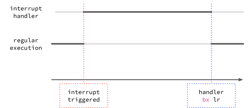
In today’s lab, this all changes. You’re going to configure a timer interrupt which will periodically “interrupt” the flow of your program, execute a special interrupt handler function, and then return back to where your “main” program was executing. Then you’ll go further by showing how the microbit can handle multiple interrupts, each with their own handler function, and how each interrupt has a priority so that interrupts can interrupt one another. It sounds confusing… but it’s not, really. You’ll get the hang of it :)
Plug in your microbit and clone your fork of the lab template and let’s get started.
Task 1: enabling the SysTick timer
A timer is a hardware component which holds a value (like a register) which counts down (or up) over time. Timers come in various shapes and sizes; some are simple and don’t have much potential for configuration, while others are extremely configurable, e.g. counting down to zero vs counting up from zero, counting at different rates, etc. Any given microcontroller can include many different timers, all with different names and configuration options, and multiple timers can be used simultaneously.
Your microbit has a timer called the SysTick timer, described in the ARMv7-M Reference Manual in Section B3.3. As with all things on your microbit, you configure the SysTick timer by reading and writing to special hardware registers. To configure and use the SysTick timer your program needs to:
-
enable the timer using the SysTick Control and Status Register (
SYST_CSR), (also set theCLKSOURCEbit to use the processor clock); -
set the SysTick Reload Value Register (
SYST_RVR)—this is the value which gets loaded into the register when it is “reloaded”, i.e. after it runs down to zero; -
read the current value of the timer register using the SysTick Current Value Register (
SYST_CVR).
You have your libraries from the last lab again under lib/. You can use the
functions and address references there to help you.
For example, if the SysTick timer is enabled (in SYST_CSR) and the value of
SYST_RVR is 0x4000 then the timer will take 16384 cycles to count down to
zero. How long this takes in wall-clock time depends on the CPU frequency
(cycles per second) of the board.
To configure the SysTick timer you’ll need to use the load-twiddle-store pattern all over again. This time, the relevant information (addresses, offsets, bits) starts at Section B3.3.2 on page 677 of the ARMv7-M Reference Manual and includes the next couple of sections as well.
At this point in the course you have the tools to read the manual and figure it out for yourself (although don’t be afraid to ask your tutor for help). Here are a few things to be mindful of:
-
remember that these are memory-mapped registers, so e.g. to read the current value into a general-purpose CPU register (e.g.
r0) you need to use anldrinstruction with the appropriate memory address -
you can find the memory-mapped addresses for both of these registers in the table in Section B3.3.2
-
to enable the timer, you’ll need to set the enable bit in
SYST_CSRand also set the clock source to use the processor clock -
even though the timer will count down automatically (once tick per clock cycle) your program still needs to be running, so make sure you’ve got an infinite “run” loop in your program
-
the initial clock speed of your microbit when you first turn it on is 64MHz so keep that in mind when you’re setting the
SYST_RVRreload value
For task 1, all you need to do is enable the SysTick timer, start it
running, and watch the values from the SYST_CVR.
Write an assembly program which configures the SysTick timer to count down from
4000000, and goes into a finished infinite loop when the timer reaches zero.
Copy your code to task1.S and push it to gitlab.
Task 2: configuring the interrupt
You may have noticed that there’s another bit in the SYST_CSR configuration
register which you didn’t set in the last task, but which looks interesting:
the TICKINT bit. The ARMv7-M Reference Manual says that this
particular bit:
indicates whether counting to 0 causes the status of the SysTick exception to change to pending
So what does this mean, exactly? Well, as discussed in lectures, an
interrupt/exception is “a signal to the processor emitted by hardware or
software indicating an event that needs immediate attention” (from
Wikipedia). If the TICKINT bit is
set in SYST_CSR, then the SysTick timer triggers an interrupt every time it
counts down to zero. Your CPU handles this interrupt by branching to an
interrupt handler which will
(hopefully) branch back when it’s finished. In words, when an interrupt comes in
then the CPU stops what it’s doing and branches somewhere else.
The ARM CPU in your microbit recognises many different types of interrupts. Some are triggered by timers, some are triggered by external peripherals (like the buttons), some are triggered by other chips or wires connected to the microbit.
All interrupts on your microbit have:
-
an index (which is just a number for identifying the source of the interrupt)
-
a priority
-
an entry in the vector table, which is a region of the microbit’s memory where the addresses (i.e. the place to branch to) of the handler routine for each interrupt
You might be wondering—where does my code branch to when the interrupt comes
in? Well, that’s what the vector table is for. It’s a special part of the
memory address space (starting at 0x0) where the addresses of the
different interrupt handler functions are stored. Think of it like a bunch of
“jump-off points”—the code for handling the interrupt will be stored
somewhere else, the vector table just has the address of the starting point for
that code.
You can see your program’s vector table in the lib/startup.S file
starting at around line 60
.section .rodata.vtable
  .word _stack_end
  .word Reset_Handler
  .word NonMaskableInt_Handler
  .word HardFault_Handler
  .word MemManage_Handler
  .word BusFault_Handler
  .word UsageFault_Handler
  .word 0
  .word 0
  .word 0
  .word 0
  .word SVC_Handler
  .word DebugMon_Handler
  .word 0
  .word PendSV_Handler
  .word SysTick_Handler
  @
  @ more entries follow...
  @
What does it mean if there’s a 0 in a particular “slot” in the vector table?
Try and find the vector table for yourself in the startup file. Look for the
.section .rodata.vtable directive—can you see how it mirrors the table from Section
B1.5.2? You can see that there’s already a SysTick_Handler label in there in
the 16th slot in the vector table, but my “hot tip” to you is that the
SysTick_Handler function isn’t very interesting at the moment, it’s just
defined to be equal to the Default_Handler (which is just an infinite loop)
down at the bottom of the file.
Your job in Task 2 is to build on the counter program you wrote in Exercise 1 and add a couple of things:
-
when you configure the timer, set the TICKINT bit as well
-
somewhere in your program, write a function (i.e. something which you can
blto and which does abx lrat the end) calledSysTick_Handler
We are setting up Systick_Handler as a function that we can bl to and which
does a bx lr at the end, however we won’t be doing the branching to this function.
Why is that?
If you set it up correctly, your Systick_Handler function will get called
every time the counter gets to zero.
Again, here are a couple of things to be careful of:
-
you’ll need to declare
SysTick_Handleras a label with.globalvisibility so that the address of yourSysTick_Handlerfunction will get used in the vector table insrc/startup.S, not the boring default one down the bottom of that file) -
similarly, make sure
SysTick_Handleris declared as a function with the usual.type SysTick_Handler, %function1 -
remember that the interrupt handler (in this case
SysTick_Handler) needs to be a function, and also to play nice and obey the AAPCS (otherwise it will mess with other parts of your program)
Using the led.S library provided, write a program which uses the
SysTick_Handler interrupt to toggle the an LED (or LEDS) on and off with a frequency of
1Hz (two toggles per second). Copy your code to task2.S and push it to gitlab.
There are a lot of moving parts here, so here are some hints and things to think about:
-
we still have the led library from last lab, so make sure that you set those up correctly (
bl init_leds) -
the board has a clock speed of 64MHz and the SYST_CVR value is reduced by 1 every clock cycle, however we only have 24 bits of space in the SYST_RVR (reload value register). What does this mean for the maximum length of time between interrupts?
-
it may be tempting to use registers to store global registers, however this is a recipe for disaster with interrupts (if you are unsure why this is the case, ask your neighbour or tutor), if you find that you are needing some kind of state between interrupts, then load and store to memory instead!
-
if you haven’t been using breakpoints, now is the time to do so. Put a breakpoint at the first instruction in your SysTick_Handler and run your code in debug mode, is it hitting the breakpoint? If so, step through your handler, is it doing what you expect?
Task 3: GPIO interrupts
Ok, so the SysTick_Handler looks after the SysTick timer interrupt, but what
about the other peripherals on your microbit? Is there a Button_Handler
for handling button presses? If not, where can you put your code to
be executed when a button is pressed?
The microbit includes a Nested Vectored Interrupt Controller (NVIC), a special bit of hardware which is responsible for watching the various bits of hardware (and software) which can trigger interrupts in your microbit.
A brief recap: remember that interrupts are a method of triggering an interruption to the sequence of assembly instructions being executed by the microbit. Configuring interrupts requires (at a minimum) enabling the interrupt and creating an interrupt handler—the function which gets called when the interrupt is triggered.
In this task we’re going to configure an interrupt that will be triggered
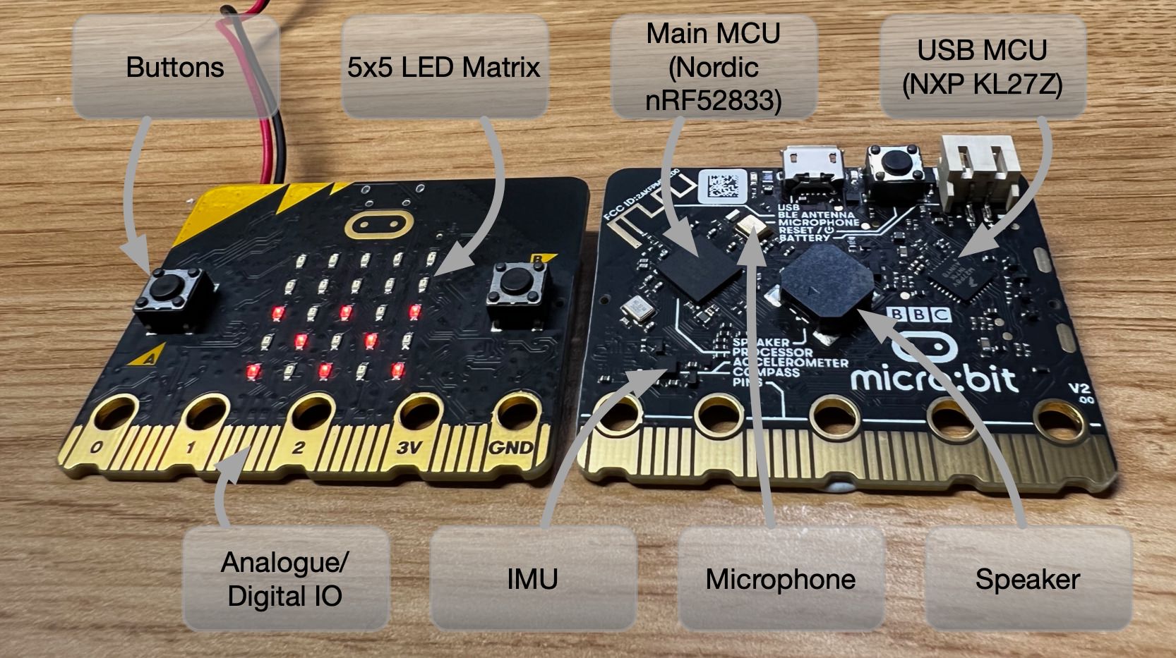
by changes on GPIO pins. The two buttons on your microbit are connected
directly to GPIO pins P0.14 (A) and P0.23 (B) as detailed in the
microbit V2 pinmap,
so if you can detect changes on these pins with an interrupt, you can run
specific code when the buttons are pushed. Finally you can use the buttons to
affect your program! This should feel pretty exciting.
Compared to the SysTick interrupt, there’s a slightly different process in configuring GPIO pins as sources of interrupts. This is because SysTick interrupt is one of the 16 “built-in” ARM Cortex interrupts—it’s not just something added by the microbit designers, it’s part of the ARM standard. The GPIO pins, on the other hand, aren’t part of a standard—each microcontroller manufacturer is free to include (or not) any number of GPIO pins on their board, and the way that they are wired into the CPU is up to them.
On your microbit, the GPIO pins are managed through the GPIO Tasks and Events Module (GPIOTE), this is described in Section 6.9 of the nRF52833 Product Specification. Out of “Tasks and Events”, events are things that can generate interrupts. Raising a GPIO-triggered interrupt is really a two-stage process (at least from the hardware’s perspective):
-
the GPIOTE module notices a change on the GPIO pins (e.g., a low-to-high voltage change) and raises an interrupt line into the NVIC
-
the NVIC deals with that interrupt, potentially saving the current register context to the stack and switching to the handler function (depending on whether the interrupt is currently enabled, whether any higher priority interrupts are already running, etc.)
So, to configure your microbit so that when you press a button an interrupt is triggered (which you can then write a handler for) you need to enable & configure the interrupt in both the GPIOTE and the NVIC. As with most things on your microbit, this is done by reading & writing the right bits in the right places to the various GPIOTE & NVIC configuration registers.
There are often more things to configure (i.e. GPIO pins) than there are bits in a 32-bit register—can you guess how the designers of the microbit get around this limitation?
Copy the code below to your main.S file (NB, this code is from the first
lecture this week, so if you didn’t see that maybe go back and watch it).
.syntax unified
.global main
@ GPIOTE Constants
.set GPIOTE_EVENTS_IN0, 0x40006100
.set GPIOTE_INTENSET, 0x40006304
.set GPIOTE_CONFIG0, 0x40006510

@ NVIC Constants
.set NVIC_ISER0, 0xE000E100

.type main, %function
main:
  @ 0: init leds
  bl init_leds
  @ 1: Configure GPIOTE_CONFIG[0]
  @ Need to setup: mode, pin, port, polarity in the configuration register for GPIOTE[0]
  @ Section 6.9.4.8 in nRF52833 reference manual
  @ mode = 1 (event), pin = 14 and port = 0 (P0.14 = Button A), polarity = 1 (LoToHi)
  ldr r0, =GPIOTE_CONFIG0
  ldr r1, =(1 | 14 << 8 | 0 << 13 | 1 << 16)
  str r1, [r0]

@ 2: Enable Interrupt for GPIOTE[0] (id = 6)
  @ S6.9.4.6 in nRF52833 reference manual
  ldr r0, =GPIOTE_INTENSET
  ldr r1, =0b1
  str r1, [r0]

@ 3: enable GPIOTE (interrupt #6 = NVIC_GPIOTE_ID) in NVIC_ISER0
  @ NVIC_ISER0: B3.4.4 in ARMv7-M Reference Manual
  ldr r0, =NVIC_ISER0
  ldr r1, =(1 << 6) @ set the 6th bit since NVIC_GPIOTE_ID = 6
  str r1, [r0]

loop:
  nop
  b loop
.size main, .-main


.global GPIOTE_IRQHandler
.type GPIOTE_IRQHandler, %function
GPIOTE_IRQHandler:
  @ setup a breakpoint here to check when the interrupt occurs.
  @ interrupt code goes here
  @ clear event
  ldr r0, =GPIOTE_EVENTS_IN0
  ldr r1, =0
  str r1, [r0]
  nop
  bx lr
.size GPIOTE_IRQHandler, .-GPIOTE_IRQHandler
In the code above, there are four setup steps:
-
Configure the GPIOTE channel 0 to to be in “event” mode, associate with GPIO pin 14 and port 0 (the pin and port of the A button), and to to listen for low-to-high voltage events (polarity = 1). Look in the nRF52833 specification section 6.9.4.8 to see how this register works. We’ve cleverly set up the config register in one line using some assembly directives.
-
Enable interrupts for events from GPTIOTE channel 0. This means just setting bit 0 in the GPIOTE “Interrupt Enable Set” register. Easy peasy. Note that if you want to disable interrupts from a GPIOTE channel you need to use the “Interrupt Enable Clear” register instead (
0x40006308). -
Enable the GPIOTE interrupt in the NVIC, its ID number is “6”. For this you need to set bit “6” in the NVIC’s Interrupt Set Enable Register (ISER; see B3.4.4 in the ARMv7-M Reference Manual). We use 6 as the id because the GPIOTE interrupt is at index 6 of the nrf52833 specific interrupts in the vector table.
-
implement a function called
GPIOTE_IRQHandlerand make sure you have the.global GPIOTE_IRQHandlerdirective.
So far so good, and this means that when your program is running, the if you
click button A, your microbit will end up executing the GPIOTE_IRQHandler.
One extra detail here is that you need to clear the record of the event that
triggered the interrupt. This means clearing the GPIOTE_EVENT_IN0 register.
If you don’t do this, the interrupt will happen over and over again!
This last section here (GPIOTE_EVENT_IN0) is basically us telling the CPU
that we have “handled” the interrupt and that it no longer needs to trigger it.
However, why didn’t we need to do this when it came to the Systick interrupt?
Use the above code to write a program where pressing button A toggles an LED on
and off, making sure you understand how the code works. Now, to test your
understanding, change the code so that it works with both button A and button B!
(Button B is on GPIO pin P0.23). Copy your code to task3.S and push it to gitlab.
Task 4: interrupt priorities
What happens when you are busy handling an interrupt and another interrupt happens? In this task you will construct such a scenario and see how interrupt priorities work.
Copy your Systick configuration code from task2.S and use the following code as
the SysTick_Handler function:
.global SysTick_Handler
.type SysTick_Handler, %function
SysTick_Handler:
  mov r0, 0b01111
  bl write_column_pins
  mov r0, 0b10000
  bl write_row_pins
SysTick_Handler_infloop:
  nop
  b SysTick_Handler_infloop
.size SysTick_Handler, .-SysTick_Handler
This handler just turns on the bottom right LED and then goes into an infinite loop. The effect is that when the first SysTick interrupt happens, control flow will get stuck in this handler code.
This is actually a bad idea for writing an interrupt handler. Usually you want the interrupt handling to be quick (it’s supposed to interrupt the flow of execution, but not block it forever). But it’s useful to do it this way to see how interrupt priorities work.
Now if you press button A when the LED is on, what happens?
Do you remember that the N in NVIC stands for nested? This means that the interrupts can happen inside of one another. Here’s a diagram to show what it might look like:
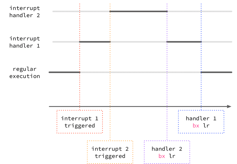
This isn’t the full story, though—the microbit doesn’t always “kick out” the
currently running interrupt for the new one, it depends on the priority. On the
microbit (as in life) some things are more important than others, and each
interrupt has a priority associated with it. On your microbit, this priority
is represented by a 4-bit number, with 0 being the highest priority and 15 being
the lowest. When an interrupt handler is running and a new interrupt is
triggered, it will only preempt (i.e., interrupt) the currently running interrupt
handler if the priority is lower. If it’s the same or higher, that interrupt
handler will be run once the currently running one finishes (i.e. returns with
bx lr).
If your other LED from task 3 doesn’t turn on when you press button A and the bottom right LED is on, this means that either the SysTick interrupt has the same or higher priority (i.e. a smaller number as the priority value) than the GPIOTE interrupt. To change the interrupt priority so that you can click the second LED on even when the first one is blinking (i.e. when the SysTick interrupt handler is running) you’ll need to lower the priority (give a higher number) to the SysTick interrupt.
Because the two interrupts (the SysTick timer interrupt and the GPIOTE interrupt) have some differences as mentioned earlier (one is part of the core ARM Cortex standard, one is a microbit-specific thing) you need to set their interrupt priorities in slightly different places:
-
for the SysTick interrupt, you can set the interrupt priority by writing bits 29-31 of the System Handler Priority Register 3 (
SHPR3, base address0xE000ED20) described in B3.2.12 of the ARM architecture reference manual -
for the GPIOTE interrupt, you can set the interrupt priority by writing bits 21-23 of the NVIC interrupt priority register (
NVIC_IPR1, base address=0xE000E404)
If you’re wondering how to figure out exactly which bits to set to control the priorities, that’s ok, it’s weird. Different Cortex-M4 CPUs have different numbers of priority bits available with up to a maximum of 8-bits which is the size of the fields in the control registers. On the microbit, we only have 3-bits available (7 different priority levels), and (weirdly) it’s the high three bits. So for any 8-bit priority field, you have to write bits 5-7. (How do we know? It’s in the nRF52833 manual section 4.1.2 “CPU and support module configuration”). You can read more about interrupt priorities here and in this article.
Modify the priority of your SysTick interrupt handler so that it does get
preempted by the GPIOTE handler and your second LED comes on when the first is on.
Copy your code to task4.S and push it to gitlab.
Extra Tasks:
More Buttons
So far you have only worked with button A (GPIO P0.14) and B (GPIO P0.23)
to trigger the same logic. But your microbit also has four pads designed
for touch sensitive pressing (the central “logo”, and ring connectors 0, 1, and
2).
Can you do something more interesting with these other buttons? It could be something simple like toggling different LEDs based on what button is pressed, but the idea is to get started with more complicated interrupt arrangements.
Buttons A and B are triggered by a low-to-high event, and the touch sensors should be high-to-low.
You can use a different channel of the GPIOTE module for each button if you
like, but you will then need to sort out which “kind” of an interrupt (button
A, B, logo, or ring 0, 1, or 2) it is in the GPIOTE interrupt handler, you can
do that by checking which EVENT_IN[n] register has the lowest bit set, which
indicates that the event was triggered by the pin associated with that channel.
-
Again, this ensures that the thumb-mode (interworking) bits are set correctly and that the alignment is ok for the function to be used as an interrupt handler, and just generally handles the gory details about the ARMv7 standard for these things. ↩