Twenty Three Hundred
Networks
Dr Charles Martin
Semester 1, 2022

Week 9: Networks
Outline
Admin Time
Little wires!
Assignment 2 presubmission!
Midsem feedback: aiming for Monday 9/5.
Quiz 2 opens next week!
Basic concepts
We want to communicate with others
What’s so hard about this?
communication is easy if both ends of the communication can share memory/registers
e.g., function calls, shared global variables (in the .data section)
but most of the time that’s not the case
Data Requires Difference
talk
on a wire carrying electrical signals, what might difference look like? how many different ways could you achieve it?
Aspects of network communication
there are a few fundamental “dimensions” to a given communications network
- transmission medium
- communications protocol(s)
- topology
these are all (at least partially) orthogonal
What’s a node?
the term node is used a lot when talking about networks
a node is anything which communicates on the network
- servers
- computers
- mobile phones
- IoT devices
- nanobots
Transmission medium
lots of options here:
- electrical voltages on a wire (or several wires)
- co-axial cable
- twisted-pair cable
- EM waves in the air
- light in an optic-fiber cable
(anything else?)
Physics refresher
In case you haven’t studied physics…
- a voltage is a relative measurement, it’s a voltage difference between two endpoints
- the ground pins are the reference point on your microbit
- sometimes the values matter (low or high,
0or1) and sometimes the transitions are most important (rising/falling edge triggers)

ReaccNet v1
can we communicate with reaccs?
knock, knock!
who’s there?
Communication protocol
a set of rules about what to “say” and how to understand the responses
in a computing context:
- how big are the messages?
- lsb first, or msb?
- is there metadata? how is it stored?
both sides must agree!
how are network “protocols” like social protocols? What happens when social protocols go wrong?
Circuit-switched networks
circuit-switched means nodes set up & use a dedicated connection (physical or logical)
example: phone lines in ye olden days—to route the phone call to the right place, the switchboard operator would literally make a physical connection between the caller & the receiver
Bell System international switchboard in 1943
Packet-switched networks
packet-switched means data transmitted over the network is segmented into packets (or frames)
these packets contain both:
- a payload (what you want to send)
- an address (who you want to send it to)
these days, most network protocols are packet-switched
this allows different nodes to share the same physical connections (multiplexing)
ReaccNet v2
can we send a message in packets?
Directions of information flow
- simplex means information only flows one way: from sender to receiver
- half-duplex means information can flow both ways, but not at the same time
- full-duplex means information can flow both ways simultaneously
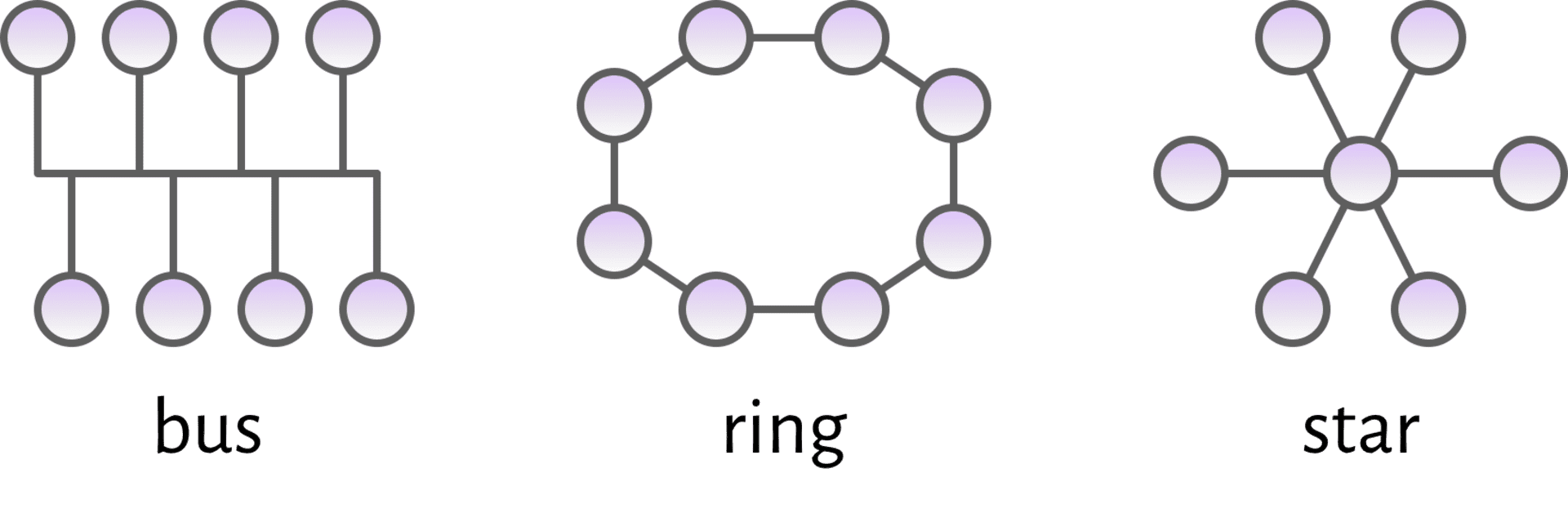
Topology
topology is the way that the nodes are connected to one another (both physically and logically)
there are several different ways to connect the nodes together, what are the consequences of different topologies?
ReaccNet v3
how about sending a message to a specific node?
circuit-switched vs packet-switched?
Serial vs parallel
| serial | parallel |
|---|---|
| data is sent one-bit-at-a-time | multiple bits sent simultaneously (e.g. multiple wires) |
| fewer bits sent per signal, but simpler | need to keep all the connections in sync |

Timing & synchronisation
There are two main approaches: synchronous and asynchronous. (See Sparkfun Serial Turorial)
Within the world of serial connections this looks something like this:
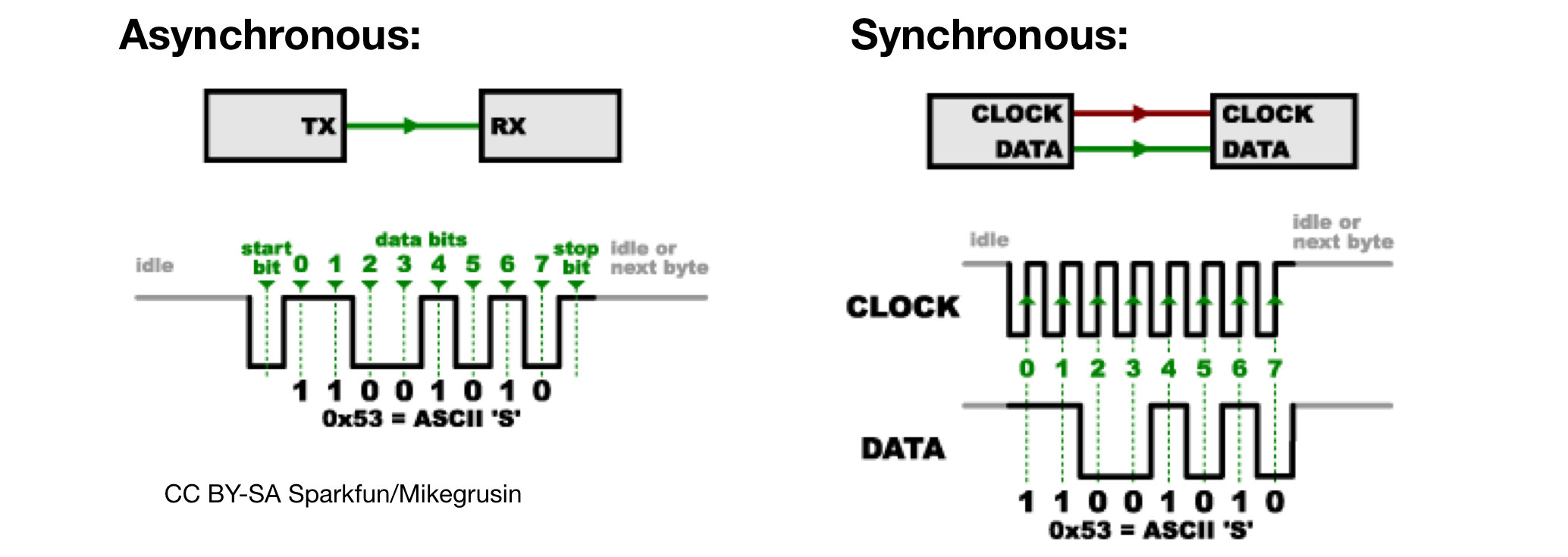
Synchronous vs Asynchronous
Synchronous:
- need to have a clock line (extra wire)
- simple to implement in hardware
- very widely used in simple devices, e.g., SD cards (can) use SPI
Asynchronous:
- transmitter and receiver both need a clock/timer and they need to pre-agree on the speed
- only need one wire (and ground) - useful for microbits!
Let's do some asynchronous data sending!
What do we have to do?
Decide on a rate of bits-per-second (baudrate)
Send a start bit (set GPIO low)
Send the 8 bits of a byte (changing GPIO)
Send a stop bit (set GPIO high)
Not too hard, but we’ll need an oscilloscope to see what we are doing!
Serial Experiments Charles
Let’s have a look at some bytes…
0x00
0xFF
0b01010101
Musical Networks
Are there any network protocols dedicated to musical instruments?
Can we set them up to work on a microbit?
MIDI
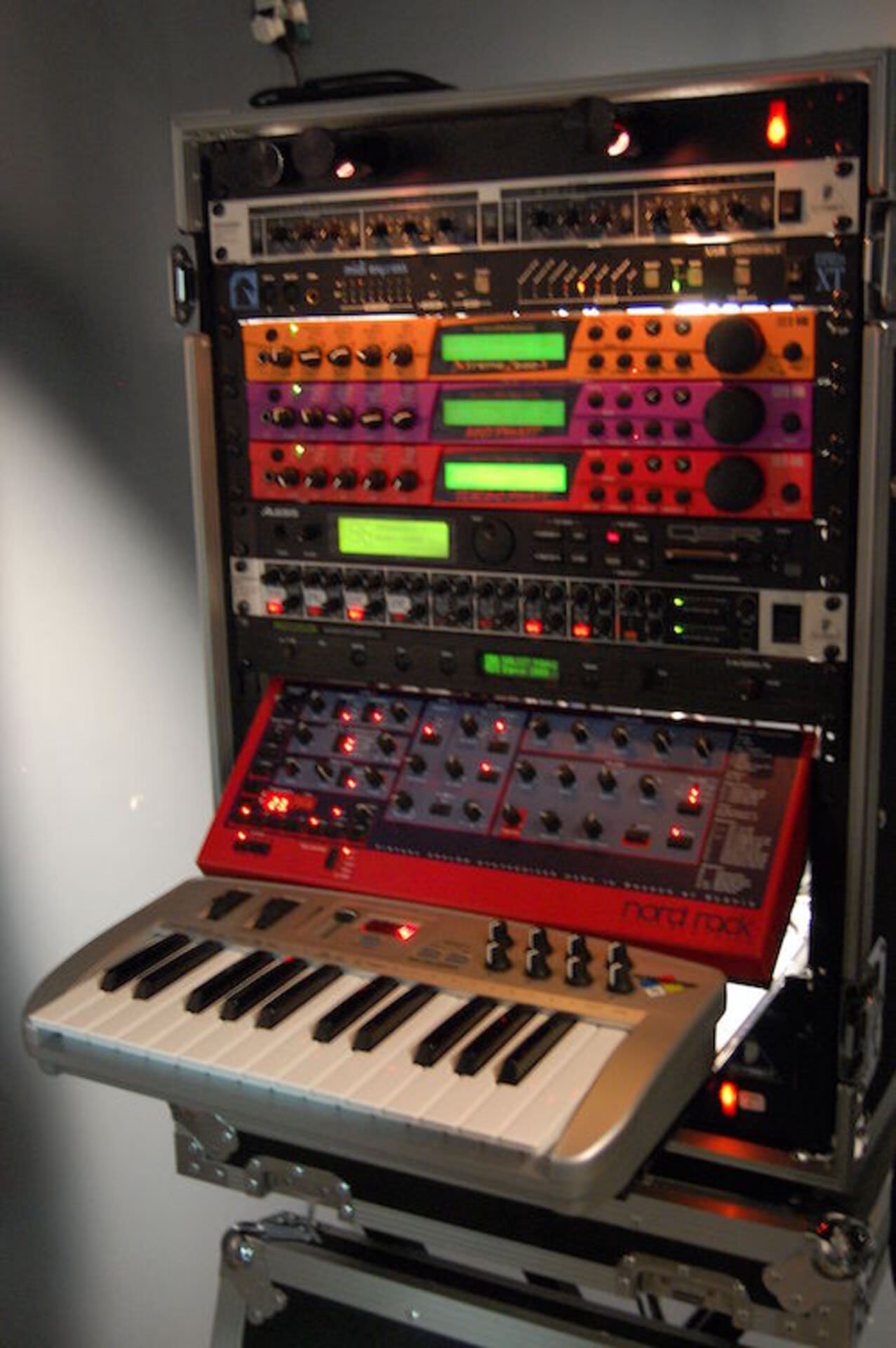
“Musical Instrument Digital Interface” (1981)
A way to send musical “instructions” to a synthesiser.
E.g., (CC BY 2.0, Blurred Ren)
MIDI medium and frames
- MIDI 1.0:
- Sent over UART (basic serial) connection
- 31250 bits per second
- each frame has one start bit (0), 8 data bits, one stop bit (1)
- MIDI tutorial on Sparkfun
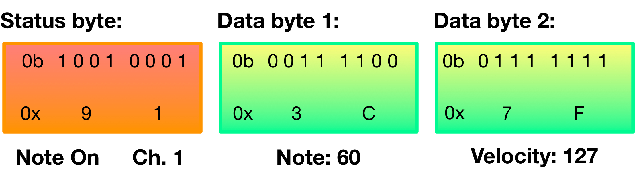
MIDI messages
- One status byte, one or more data bytes
- Status byte has a “status” (4 bits) and (usually) a channel or address (4 bits)
- Data byte is a
0followed by a 7 bit number.
Sorting concerns into layers
Implementing a connection between two devices seems to be getting messy…
specific information about bit-level signals
special timing considerations
application-specific representations of information within and between bytes
Is there some way to separate concerns here?
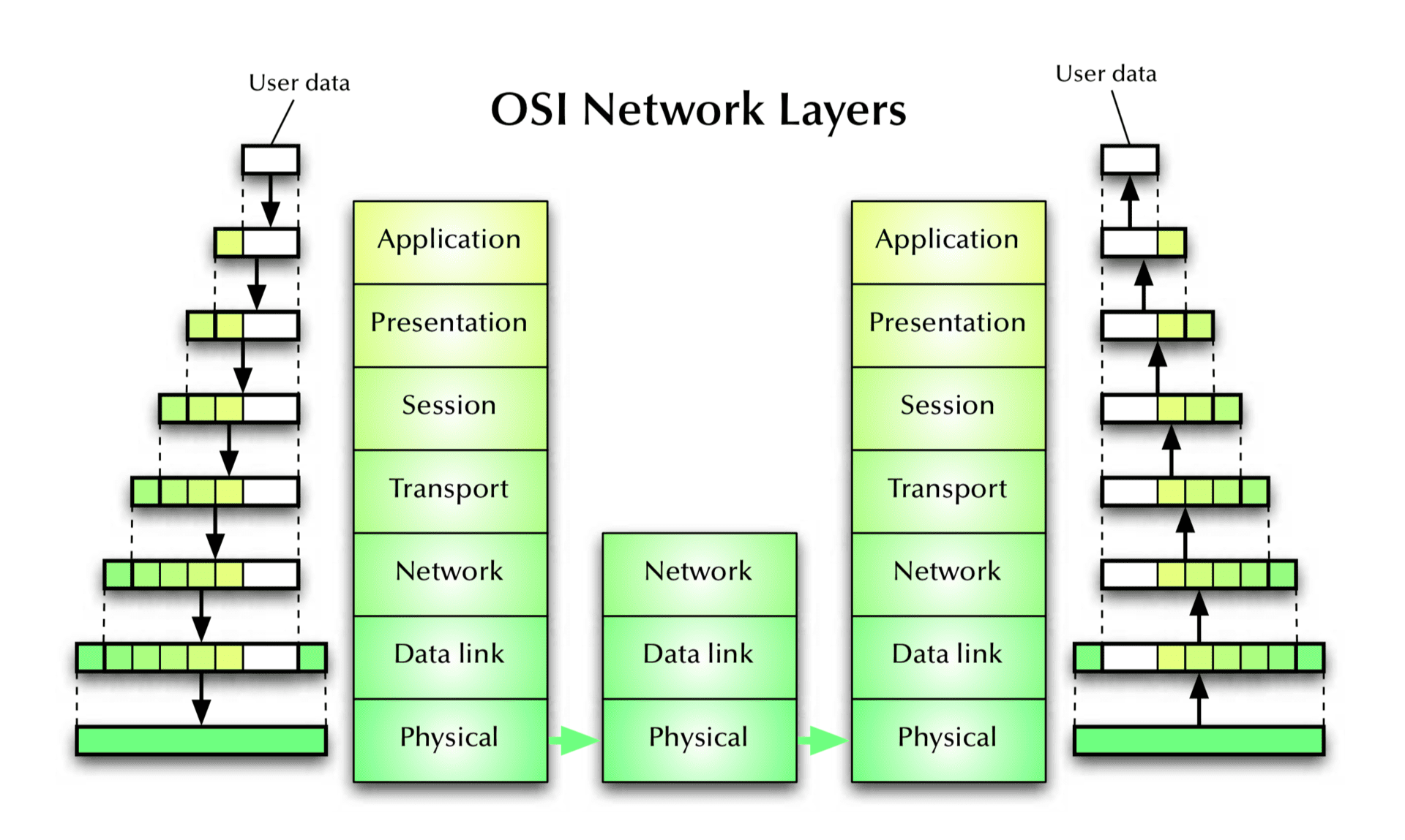
7-layer OSI model
The Open Systems Interconnection model (OSI model) is a conceptual model that characterizes and standardizes the communication functions of a telecommunication or computing system without regard to its underlying internal structure and technology (from Wikipedia)
standardised in 1977: 7 layer architecture, connection oriented
not often implemented in full, but concepts and terminology widely used.
Layer 1: physical layer
- Service: Transmission of a raw bit stream over a communication channel
- Functions: Conversion of bits into electrical or optical signals
- Examples: X.21, Ethernet (cable, detectors & amplifiers)
Layer 2: data link layer
- Service: Reliable transfer of frames over a link
- Functions: Synchronization, error correction, flow control
- Examples: HDLC, LAP-B, LAP-D, LLC
Layer 3: network layer
- Service: Transfer of packets inside the network
- Functions: Routing, addressing, switching, congestion control
- Examples: IP, X.25
Layer 4: transport layer
- Service: Transfer of data between hosts
- Functions: Connection establishment, management, termination, flow-control, multiplexing, error detection
- Examples: TCP, UDP, ISO TP0-TP4
Layer 5: session layer
- Service: Coordination of the dialogue between application programs
- Functions: Session establishment, management, termination
- Examples: RPC
Layer 6: presentation layer
- Service: Provision of platform independent coding and encryption
- Functions: Code conversion, encryption, virtual devices
- Examples: ISO code conversion, PGP encryption
Layer 7: application layer
- Service: Network access for application programs
- Functions: Application/OS specific
- Examples: APIs for mail, ftp, ssh, scp, discovery protocols
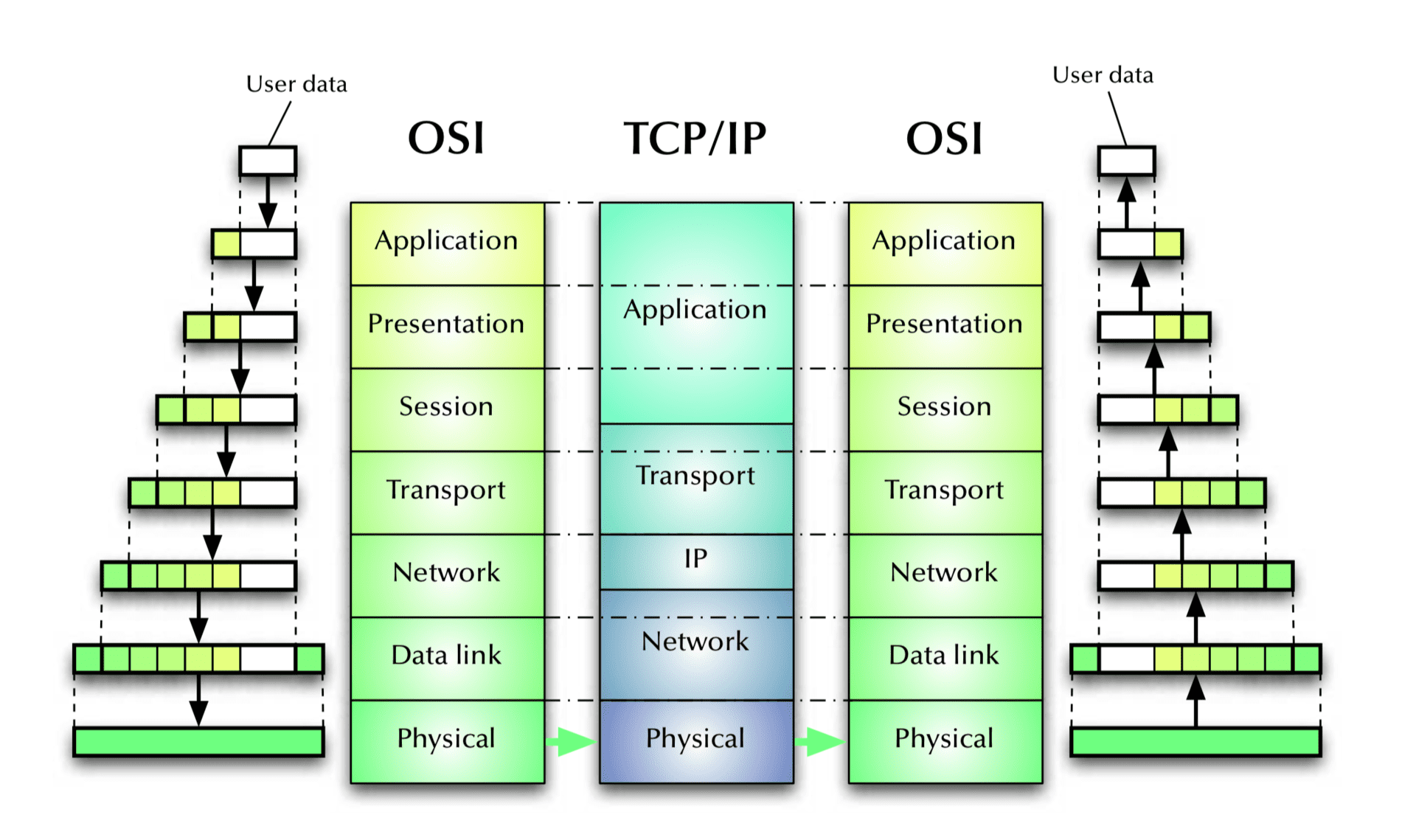
TCP/IP, not an ideal fit with OSI
What about synchronous? Did we miss that? And what else is on the microbit?
SPI: Serial Peripheral Interface
- used by gazillions of devices… and it’s not even a formal standard!
- speed only limited by what both sides can survive
- synchronous protocol, so it’s quite easy to implement in software
(NB: the pin terminology of SPI has changed recently to use more inclusive language).
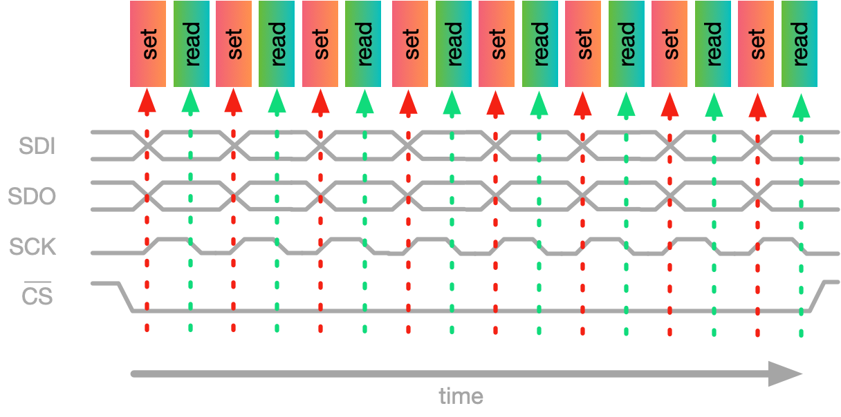
SPI connections
full duplex, 4-wire, flexible clock rate
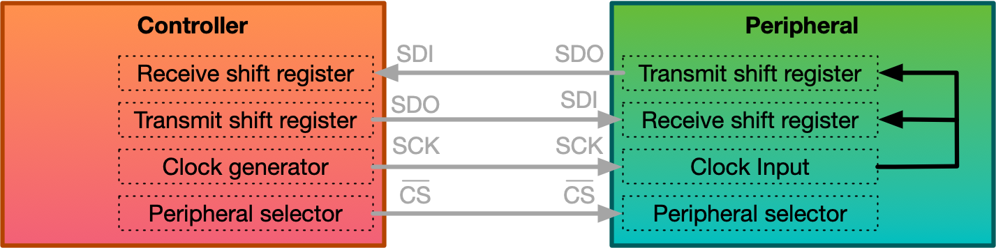
(SDI: “Serial Data In”, SDO: “Serial Data Out”, SCK: “Serial Clock”, CS: “Chip Select”)
SPI timing and data
What can you do with Synchronous Connections?
-
Read/Write to peripherals (e.g., motion sensor) with I2C (Inter-Integrated Circuit Protocol)
Ethernet / IEEE 802.3
Local area network (LAN) developed by Xerox in the 70’s
- 10 Mbps specification 1.0 by DEC, Intel, & Xerox in 1980
- First standardised as IEEE 802.3 in 1983 (10 Mbps over thick co-ax cables)
- currently 1 Gbps (802.3ab) copper cable ports used in most desktops and laptops
- currently standards up to 100 Gbps (IEEE 802.3ba 2010)
- more than 85% of current LAN lines worldwide (according to the International Data Corporation)
See Ben Eater’s youtube channel are great
Bluetooth LE
Microbit has a “Bluetooth® 5.1, IEEE 802.15.4-2006, 2.4 GHz transceiver”
- wireless data
- originally from 1998, but 5.1 released in 2019
- typically for connecting wireless connections between multiple devices with one user: e.g. headphones, speakers, mouse, keyboard, remote control, smart watches, etc.
How does it work? Let’s look at section 6.18 of the nRF52833 manual!
Further study
this was a really high-level overview; a whirlwind tour
to go deeper, you could take COMP3310
What communication hardware is on the microbit?
Last time, we sent bytes manually with a timer.
The microbit has hardware to help us.
Let’s try the same thing with the UART hardware.
Sending Bytes with UART: Preparation
.set ADR_UART, 0x40002000
.set OFS_UART_STARTTX, 0x008
.set OFS_UART_TXDRDY, 0x11c
.set OFS_UART_ENABLE, 0x500
.set OFS_UART_PSEL_TXD, 0x50c
.set OFS_UART_TXD, 0x51c
.set OFS_UART_BAUDRATE, 0x524
.set OFS_UART_CONFIG, 0x56c

.type setup_output, %function
setup_output: @ Set RING0 (P0.2) to output
    ldr r0, =ADR_P0
    ldr r1, =OFS_GPIO_DIRSET
    ldr r2, =(0b1 << 2)
    str r2, [r0, r1]
    bx lr
.size setup_output, . - setup_output

.type turn_on_ring_0, %function
turn_on_ring_0: @ Set RING0 (P0.2) to high
    ldr r0, =ADR_P0
    ldr r1, =OFS_GPIO_OUTSET
    ldr r2, =(0b1 << 2)
    str r2, [r0, r1]
    bx lr
.size turn_on_ring_0, . - turn_on_ring_0
Sending Bytes with UART: configuring UART
  @ 0. Set RING0 (P0.2) to output and high
  bl setup_output
  bl turn_on_ring_0
  @ 1. Clear UART config register
  ldr r0, =ADR_UART
  ldr r1, =OFS_UART_CONFIG
  mov r2, 0x0 @ default values
  str r2, [r0, r1]

  @ 2. set baudrate
  ldr r1, =OFS_UART_BAUDRATE
  ldr r2, =0x00800000 @ 31250 baud
  str r2, [r0, r1]

  @ 3. set tx pin to RING0 (P0.2) - =(0x0 << 31 | 0x0 << 5 | 0x2) @ connect (clear 31), port 0, pin 2
  ldr r1, =OFS_UART_PSEL_TXD
  ldr r2, =(0x0 << 31 | 0x0 << 5 | 0x2) @ connected, port 0, pin 2
  str r2, [r0, r1]

  @ 4. enable UART
  ldr r1, =OFS_UART_ENABLE
  ldr r2, =4
  str r2, [r0, r1]
Sending Bytes with UART: sending the bytes
  @ 5. put byte to send into txd
  ldr r1, =OFS_UART_TXD @ this is the transmit buffer -- the byte to actually send
  mov r2, 0xFF @ <--- this is the byte to be sent!
  str r2, [r0, r1]

  @ 6. set starttx task
  ldr r1, =OFS_UART_STARTTX
  mov r2, 1
  str r2, [r0, r1]
- Once
starttxtask has started, whenver you put a byte intoUART_TXD, that byte will be sent. - Just need to check
TXDRDYregister to make sure previous byte has completed sending. - Can also set
TXDRDYto generate an interrupt if you want