Twenty Three Hundred
ALU Operations
Dr Charles Martin
Semester 1, 2022

Week 2: ALU operations
Outline
A tour of your microbit
There's lots of stuff on your microbit
Way more than you can master in a one-semester course…
… but you’ll understand a lot more about it by the end of the course than you do now
Instructions
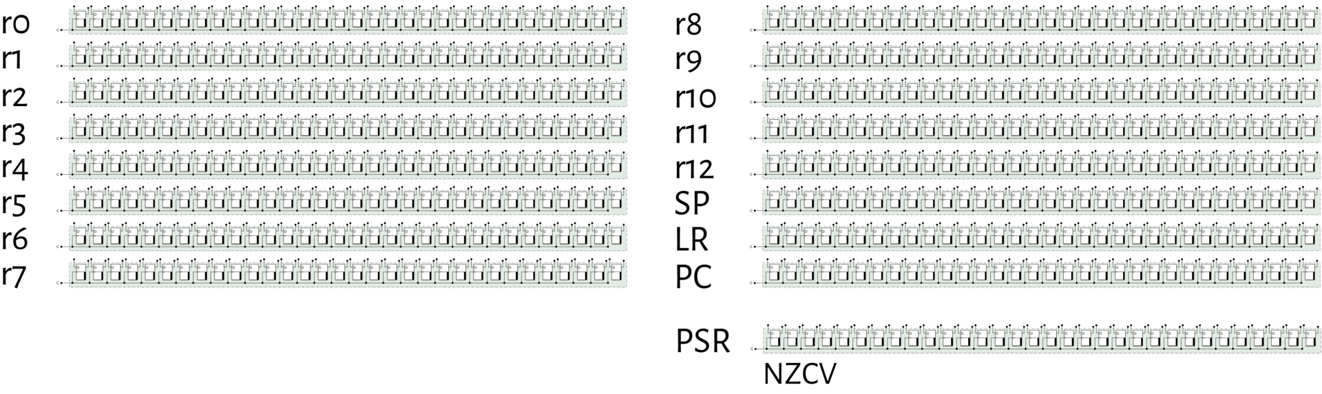
Recap: a 32-bit register
It’s just a bunch of sequential (stateful) circuits hooked up to a common clock line (like we discussed last week)

Oh no more registers!
Registers are usually grouped in banks (groups). Here are the 16 general-purpose registers in your microbit’s CPU
talk
Back to 1 + 2, but this time, in C
int x = 1 + 2;
How do you think this might work in silicon?
How does this relate to the gates and things that we looked at last week?
Breaking it down
int x = 1 + 2;
So, there are three steps:
- get a
1into a register - get a
2into another register - tell the ALU to add them and put the result into another register
First assembly code
@ move a 1 into r0
movs r0, 1
@ move a 2 into r1
movs r1, 2
@ add them together, put result in r2
adds r2, r0, r1
Let's do it for reals
Addition in machine code
adds <Rd>, <Rn>, <Rm>
The add instruction is encoded into this 16-bit value
| 15 | 14 | 13 | 12 | 11 | 10 | 9 | 8 | 7 | 6 | 5 | 4 | 3 | 2 | 1 | 0 |
|---|---|---|---|---|---|---|---|---|---|---|---|---|---|---|---|
| 0 | 0 | 0 | 1 | 1 | 0 | 0 | m | m | m | n | n | n | d | d | d |
- the
0001100part is the operation code (opcode) - the other parts (
m,n,d) are the arguments
Example: addition in machine code
adds r2, r0, r1
Here, Rd is r2, Rn is r0 and Rm is r1
| 15 | 14 | 13 | 12 | 11 | 10 | 9 | 8 | 7 | 6 | 5 | 4 | 3 | 2 | 1 | 0 |
|---|---|---|---|---|---|---|---|---|---|---|---|---|---|---|---|
| 0 | 0 | 0 | 1 | 1 | 0 | 0 | m | m | m | n | n | n | d | d | d |
So what does the instruction look like?
| 15 | 14 | 13 | 12 | 11 | 10 | 9 | 8 | 7 | 6 | 5 | 4 | 3 | 2 | 1 | 0 |
|---|---|---|---|---|---|---|---|---|---|---|---|---|---|---|---|
| 0 | 0 | 0 | 1 | 1 | 0 | 0 | 0 | 0 | 1 | 0 | 0 | 0 | 0 | 1 | 0 |
Back to the ALU, how would this code fit?
| 15 | 14 | 13 | 12 | 11 | 10 | 9 | 8 | 7 | 6 | 5 | 4 | 3 | 2 | 1 | 0 |
|---|---|---|---|---|---|---|---|---|---|---|---|---|---|---|---|
| 0 | 0 | 0 | 1 | 1 | 0 | 0 | 0 | 0 | 1 | 0 | 0 | 0 | 0 | 1 | 0 |
Assembly code vs machine code
There’s a direct mapping between the two, although the microbit only understands the machine code (of course!)
We use assembly code because:
- it’s easier for humans to read/write
- it gives a little bit of flexibility (as we’ll see shortly)
The assembler
The word assembly/assembler is way overloaded in computer architecture. It might mean
- the human-readable assembly code, e.g.
adds r2, r0, r1 - the program for
encoding that human-readable statement into the binary machine code (the
1s and0s) - the process of doing that conversion
GNU Assembler
The toolchain we use in this course uses GAS: the GNU Assembler (part of binutils)
The assembler determines the acceptable syntax for your assembly .S files
(there are multiple syntaxes—there’s no one “assembly language”, even for a
specific board)
talk
So, registers are just like variables… right? Discuss with your neighbour
The move instruction
Ok, let’s get back to our 1 + 2 program. adds lets us add the numbers in
the registers, but how do we get the numbers (i.e. 1 and 2) into the
program?
movs <Rd>, #<imm8>
| 15 | 14 | 13 | 12 | 11 | 10 | 9 | 8 | 7 | 6 | 5 | 4 | 3 | 2 | 1 | 0 |
|---|---|---|---|---|---|---|---|---|---|---|---|---|---|---|---|
| 0 | 0 | 1 | 0 | 0 | d | d | d | i | i | i | i | i | i | i | i |
The clever idea: store the immediate value inside the instruction!
talk
if this is the move instruction:
| 15 | 14 | 13 | 12 | 11 | 10 | 9 | 8 | 7 | 6 | 5 | 4 | 3 | 2 | 1 | 0 |
|---|---|---|---|---|---|---|---|---|---|---|---|---|---|---|---|
| 0 | 0 | 1 | 0 | 0 | d | d | d | i | i | i | i | i | i | i | i |
what does the following instruction do?
| 15 | 14 | 13 | 12 | 11 | 10 | 9 | 8 | 7 | 6 | 5 | 4 | 3 | 2 | 1 | 0 |
|---|---|---|---|---|---|---|---|---|---|---|---|---|---|---|---|
| 0 | 0 | 1 | 0 | 0 | 1 | 0 | 0 | 0 | 0 | 0 | 0 | 1 | 1 | 0 | 1 |
So what instructions are possible?
That’s determined by the Instruction Set Architecture (ISA)
Also specifies the number & size of the registers, memory and a few other things
Many CPUs share the same instruction set (that’s kindof the point)
ARM Cortex-M series CPU
From the ARM website:
The Arm Cortex-M processor family is a range of scalable, energy efficient and easy-to-use processors that meet the needs of tomorrow’s smart and connected embedded applications
The microbit has a Cortex-M4 CPU
ARMv7 reference manual
The microbit (like all Cortex-M series processors) uses the ARMv7-M ISA
You’ll be looking at this a lot in the course—whenever you need more info than the cheat sheet provides
The ARMv7 cheat sheet
It’s available from the resources page
Understanding the instruction syntax
add{s}<c><q> {<Rd>,} <Rn>, <Rm> {,<shift>}
- anything inside curly brackets
{}is optional - anything inside angle brackets
<>is a placeholder for different argument values - register arguments
Rn/Rm/Rdyou’ve seen already (e.g.r3)
Understanding the instruction syntax
add{s}<c><q> {<Rd>,} <Rn>, <Rm> {,<shift>}
- the optional
<c>suffix makes the command conditional - the optional
<q>specifies an instruction width (n/w) -
{,<shift>}means that the value in the register is bit-shifted first
Assembler syntax: optional arguments
Sometimes the syntax specifies that a register argument is optional
This doesn’t mean that those bits are missing from the encoding!
Instead, it means that the registers are re-used (overwriting what was there before)
You'll learn the syntax by using it
Especially in labs!
RISC
Reduced Instruction Set Computing (RISC) is an approach to ISA design where there are only a few instructions, and to do more complex things you just “chain them together”
The R in ARM stands for RISC
There are other options: CISC (Complex Instruction Set Computing)
Multi-width instructions
Your microbit actually supports a few different encodings for some instructions
All Cortex-M processors run in Thumb-2 mode, which includes both 16-bit and 32-bit instructions (you’ll examine this in lab 2)
The registers are always 32-bit, though
So many names!
ARM, Cortex, M, Thumb-2, oh my!
Some of this stuff was designed (well) from the start, some was added later…
There are 100+ billion of these things out there—some diversity is to be expected
The reference manual
There’s a full list of all instructions & encodings in the ARM®v7-M Architecture Reference Manual, section 7.7 (starting on p184)
It’s got all the gory details
Let’s find the mov instruction…
Questions
Instructions: Part 2
Immediate vs register instructions
Some instructions require register “arguments”: places where the bits in the encoded instruction specify which registers to read from/write to.
adds r2, r0, r1
Other instructions have immediate values (#<const>) on the cheat sheet where
the actual value is encoded in the instruction.
movs r0, 1
Some folks have been looking through the reference manual, and noticed that some instructions have both an immediate version and a register version
Example: add
Here’s add (immediate) (encoding T2, A7.7.3 in the reference manual)
| 15 | 14 | 13 | 12 | 11 | 10 | 9 | 8 | 7 | 6 | 5 | 4 | 3 | 2 | 1 | 0 |
|---|---|---|---|---|---|---|---|---|---|---|---|---|---|---|---|
| 0 | 0 | 1 | 1 | 0 | d | d | d | i | i | i | i | i | i | i | i |
Here’s add (register) (encoding T1, A7.7.4 in the reference
manual)
| 15 | 14 | 13 | 12 | 11 | 10 | 9 | 8 | 7 | 6 | 5 | 4 | 3 | 2 | 1 | 0 |
|---|---|---|---|---|---|---|---|---|---|---|---|---|---|---|---|
| 0 | 0 | 0 | 1 | 1 | 0 | 0 | m | m | m | n | n | n | d | d | d |
talk
why do we need both immediate and register versions of these instructions?
Instructions == the language of the CPU
the 1s and 0s encode the instruction
the CPU understands them (if they’re part of the language it speaks, i.e. the ISA)
the CPU does exactly what it’s told at that moment
but what about the next moment? And the one after that?
Fetch-decode-execute cycle
Recap: ARMv7-M registers
the pc register
Register 15 (r15) is a bit special in this ISA—it’s the program
counter
Imagine all the instructions in your program are lined up, one after the other…
the program counter is like a bookmark keeping track of where the CPU is up to
(for where the instructions are lined up, wait till next week)
Fetch-decode-execute
During execution, your microbit:
-
fetches the next instruction based on
pc -
decodes which operation (
add,sub, etc.) to perform (and on which registers) - executes the instruction
then it goes back to step 1 and repeats the process
the fetch-decode-execute cycle
Status flags
what’s with the s in adds
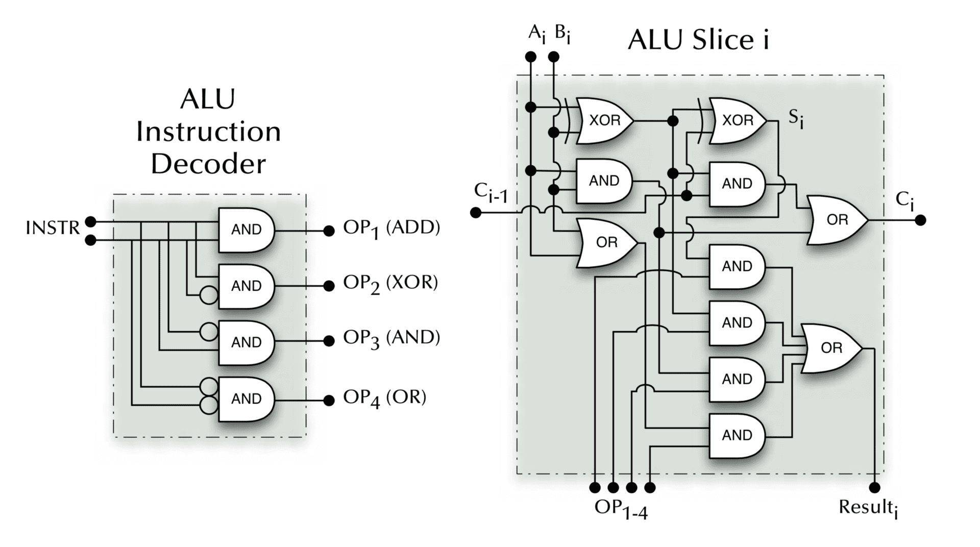
Where does the final “carry out” go?
Remember last week we wondered where the last “carry” bit goes in our ripple carry adder?
Answer: the carry flag/bit (in the status register)
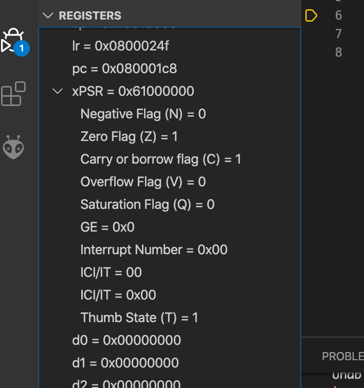
Program status register
The ARMv7-M ISA specifies a program status register (PSR) for keeping track of various important bits of state associated with the current computation
The 4 highest bits (31:28) are the NZCV flags:
- Negative
- Zero
- Carry
- Overflow
In VSCodium
“Set flags” instructions
If there’s an s on the end of the instruction, it means that the instruction
will set the flags (if appropriate) based on the result of the instruction
This is specified by a certain bit in the encoding (in some of the encodings, anyway)
You don’t have to set flags—the s is optional
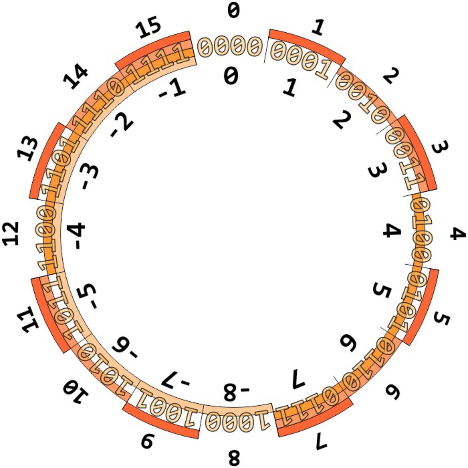
Recap: natural (unsigned) & twos-complement (signed) binary numbers
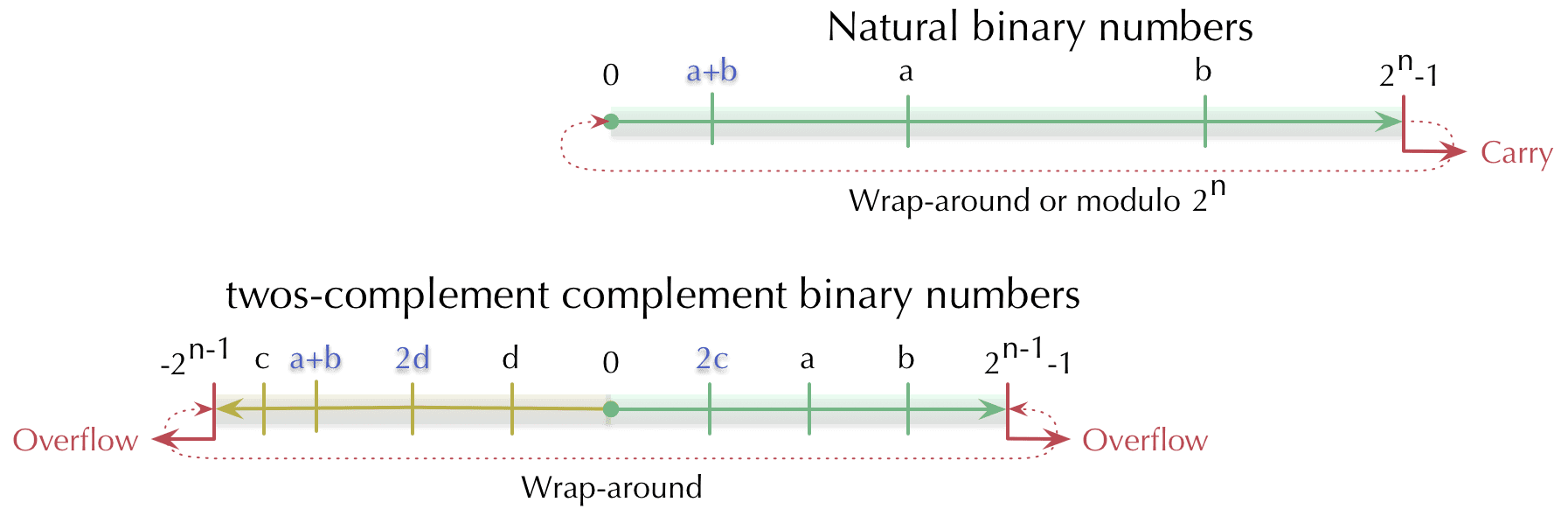
Think of the velodrome
The twos complement “circle”
Negative
This status flag is set when the result of an ALU operation is negative if interpreted as a twos complement signed integer
movs r0, 5
movs r1, 6
subs r2, r0, r1
don’t forget the s suffix
talk
movs r0, 5
movs r1, 6
subs r2, r0, r1
What flags will be set after the subs instruction is executed?
We'll demo all of these, just to be sure!
Zero
This status flag is set when the result of an ALU operation is zero
movs r5, 5
movs r6, -5
adds r4, r5, r6
Carry
This status flag is set when the result of an ALU operation requires a “carry out” if interpreted as an unsigned 32-bit integer (i.e. it requires 33 or more bits to represent)
movs r2, 0xFF000000
movs r3, 0xFF000000
adds r5, r2, r3
Overflow
This status flag is set when the result of an ALU operation would overflow the min/max value if interpreted as a twos complement signed integer
movs r0, 0x7FFFFFFF @ largest signed integer
adds r0, 1
movs r0, 0x80000000 @ smallest signed integer
subs r0, 1
adc vs add
The adc (add with carry) instruction is really similar to the add
instruction, but it also adds the current value of the carry flag to the
result
mov r1, 5
mov r2, 16
adc r3, r1, r2
talk
mov r1, 5
mov r2, 16
adc r3, r1, r2
What value will be in r3 after the above instructions are executed?
Worked example: 64-bit addition
Can we add numbers bigger than the (32-bit) word size? Yes!
- assume numbers in
r3:r2andr5:r4 - we want to store the 64-bit result in
r1:r0
adds r0, r2, r4 @ add least significant words, set flags
adcs r1, r3, r5 @ add most significant words and carry bit
More flags
The status register is 32-bit, and there are more flags than these 4—but they’re the main ones
You’ll use them (a lot!) in the week 3 lab
We’ll introduce the other flags as necessary later in the course
On purity...
Remember Haskell? Lovely pure functions—no outside state or side effects
The real world? Messy, stateful—yuck! But we can get things done
Arithmetic instructions
add{s}<c><q> {<Rd>,} <Rn>, <Rm> {,<shift>} @ Rd := Rn + Rm(shifted)
adc{s}<c><q> {<Rd>,} <Rn>, <Rm> {,<shift>} @ Rd := Rn + Rm(shifted) + C
add{s}<c><q> {<Rd>,} <Rn>, #<const>        @ Rd := Rn + #<const>
adc{s}<c><q> {<Rd>,} <Rn>, #<const>        @ Rd := Rn + #<const> + C
qadd<c><q> {<Rd>,} <Rn>, <Rm>              @ Rd := Rn + Rm @ saturated
sub{s}<c><q> {<Rd>,} <Rn>, <Rm> {,<shift>} @ Rd := Rn - Rm(shifted)
sbc{s}<c><q> {<Rd>,} <Rn>, <Rm> {,<shift>} @ Rd := Rn - Rm(shifted) - NOT (C)
rsb{s}<c><q> {<Rd>,} <Rn>, <Rm> {,<shift>} @ Rd := Rm(shifted) - Rn
sub{s}<c><q> {<Rd>,} <Rn>, #<const>        @ Rd := Rn - #<const>
sbc{s}<c><q> {<Rd>,} <Rn>, #<const>        @ Rd := Rn - #<const> - NOT (C)
rsb{s}<c><q> {<Rd>,} <Rn>, #<const>        @ Rd := #<const> - Rn
qsub<c><q> {<Rd>,} Rn, Rm                  @ Rd := Rn - Rm @ saturated