Week 5: sound and light
This lab includes in-lab assessment for the assignment 1 Pre-Submission task. Read about it how that works on the assignment presubmission page (link).
Introduction
In this week’s lab you will learn how to use functions to simplify accessing the lights on your microbit. You will also try out making some sounds with the microbit’s speaker.
This lab picks up from the end of last week’s “blinky” lab. If you didn’t
finish the lab tasks from last week, start with those before moving on to this
week’s work. We will be using the week-5 folder of the lab repo you forked
and cloned last week. If not,
here’s a link.
Task 1: LEDs and functions
At the end of last week’s lab you should have felt a warm glow of satisfaction—let there be light! But you might have noticed that a few of the steps you had to go through were pretty repetitive. For every step in blinking an LED, you were really doing one of two things:
- setting a specific bit at an offset from a base address, or
- clearing a specific bit at an offset from a base address
Wouldn’t it be good if we could “factor out” the common parts of those two
tasks, so that the code is simpler and clearer? We can do that with
functions (something you saw in the lecture this week). Remember that a
function starts with a label, and ends with the bx lr instruction. To “call”
a function you use the bl instruction to branch to the function’s label.
set_bit_0x50000000_0x514_21:
  @ code to set bit 21 of word at offset 0x514 of 0x50000000
  bx lr

main:
  @ ...
  bl set_bit_0x50000000_0x514_21
  b main
Update your top-left-LED-turning-on program from last week by writing a few
functions using the name pattern set_bit_<base>_<offset>_<index> and
clear_bit_<base>_<offset>_<index> following the example above. Your main
function is just a series of bl instructions (and “spins” in an infinite loop
at the end).
Arguments/parameters
You’ve now modularised your code (broken it up into smaller, re-usable parts),
but it’s still pretty repetitive. There’s a lot of repeated code between the
set_bit_xxxx functions.
The only difference between these repeated versions is the difference in inputs.
Therefore we can pass arguments to functions to parameterise those
functions, so that we just have one set_bit function that we call with
different “inputs”.
As discussed in the lecture on functions, we
leave values in r0-r3 before calling bl to act as “inputs” for our
functions. Consider the following sum_x_y function:
main:
  mov r0, 3   @ first argument, x
  mov r1, 2   @ second argument, y
  bl sum_x_y  @ call sum_x_y(3, 2)
  @ get result back in r0

.type sum_x_y, %function
@ args:
@   r0: x
@   r1: y
@ result: r0
sum_x_y:
  add r0, r1
  bx lr
.size sum_x_y, .-sum_x_y
The function adds the values in r0 and r1 and puts the result in r0. So
the values in r0 and r1 are arguments (or parameters—same concept,
different name). We can just leave the numbers we want to add in r0 and r1,
call the function sum_x_y, and expect the result to be in r0 after it
finishes.
Did you notice something “underhanded” going on between the caller (main) and
the callee (sum_x_y)? There is an implicit contract/agreement as to:
- which registers hold the input arguments, and
- which registers hold the result
This is called calling convention, a set of rules that all function calls are expected to adhere to. It is generally CPU architecture and programming language defined. There is more to calling convention, and it will be covered in lecture and in the next lab.
Note that there are some comments before the function about where the arguments are placed. It’s a good idea to document what these registers are expected to hold for readability and clarity’s sake.
Parameterise your set_bit and clear_bit functions so that they each take
three arguments: base address, offset and bit index. Modify your main
function so that turning an LED on and off is as easy as calling your
set_bit or clear_bit functions with the right arguments. Copy the code into
tasks/task-1.S. Commit and push your changes with the message “completed task
1”.
You may or may not have noticed that we haven’t told you to store the lr register onto
the stack–that’s cause you’re creating what are called “leaf” functions. These
leaf functions don’t call other functions, so don’t need to worry about
having lr overwritten.
Task 2: FizzBlink
For this task, you’ll make LED blinking more interesting by writing an
ARM assembly version of the classic
FizzBuzz childrens game (and a common
programming interview
question). The
only difference is that instead of printing "fizz" or "buzz" to the screen
(which you can’t do anyway, since we’re not running on the computer, you’re
running on the microbit) you’ll blink two LEDS on the board. So this new
version is called FizzBlink, I guess.
Modify your program to:
- count up from
0to100in increments of1 - if the number is divisible by
3, blink the top left light for some period of time (use your delay function) - if the number is divisible by
5, blink the top right light for some period of time - if the number is divisible by both
3and5, blink both lights
Copy the code into tasks/task-2.S. Commit and push your changes with
the message “completed task 2”.
Task 3: Draw a picture
Now you’ve had some experience turning different LEDs on the microbit on and off. It’s time to get creative and use these skills to make some pixel art.
Your task here is to draw a picture with your microbit’s pixels. Use the skills you’ve already learned above to turn on pixels that show a recognisable shape (e.g., a house or a face). You might like to use a piece of paper or a spreadsheet to help work out which LEDs to turn on to make your picture.
But wait a minute, if the microbit needs a column set to low and a row set to high to turn on one LED, doesn’t that put some limitations in what LEDs can turn on and off together? With another member of your lab, talk about which LEDs could possible turn on together, and how complicated a picture can possibly be. Can you work out any work-arounds to display any type of picture?
Once you have a picture being displayed, show it to some other students in your lab. If you’re on online, snap a photo of it to share to your lab’s channel.
Copy your picture-drawing code into tasks/task-3.S. Commit and push your changes with
the message “completed task 3”.
Task 4: Make some byte beats
Now we’re going to make some sound with our microbits! This task is different
than the LED tasks because we have provided a lot of code to help get sound
working on a microbit. Specifically we have a basic audio library (audio.S)
included in the lab pack this week written by COMP2300 tutor Benjamin Gray1.
The idea of audio.S is to enable sample-by-sample audio playback on a
microbit. This is a very low level way of thinking about audio, but it’s
quite fun (as you will see in a minute). Digital sound is defined by “samples”,
that is a sequence of numbers over time that define how much a speaker cone
should be pulled or pushed to make a sound in the air that humans can hear. We
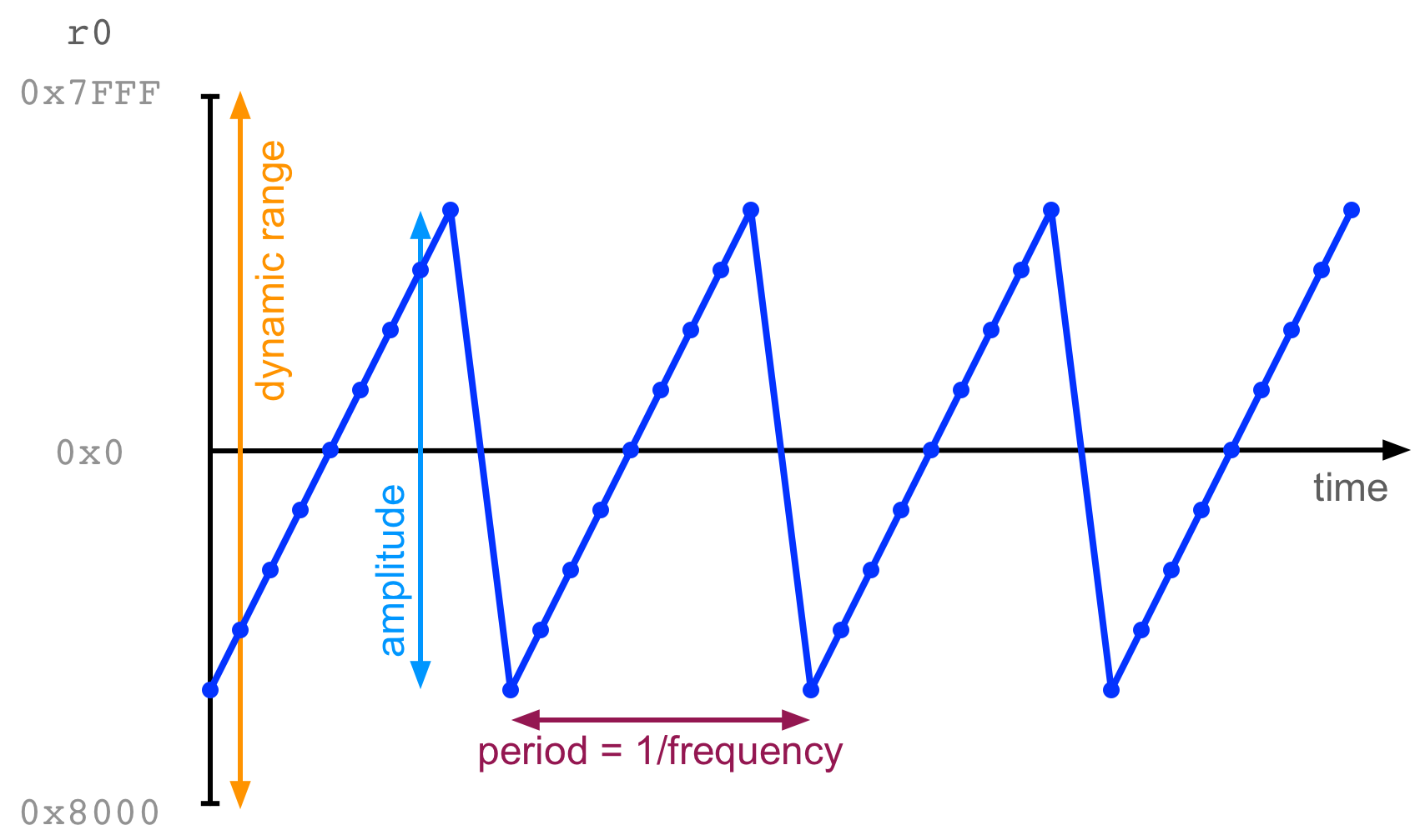
sometimes visualise digital sound waves like this:
In that image, the little points each indicate a sample, that is a number
stored in r0. The x-axis is time, and the y-axis is the number in r0. Over
time, samples move in a repeating saw-tooth pattern, creating a sound. (We’re
going to do this on the microbit in a second).
You can open up audio.S and have a look at how it works (it’s well commented
and an excellent example of good assembly style). There are two functions
that are going to be important to get sound working:
-
audio_init: this function sets up sound on the microbit which basically means setting the speaker (GPIO P0.00) to output, enabling PWM (pulse width modulation) on this pin, and setting up some buffers and timers to ensure smooth audio. -
audio_play_sample: this function takesr0as an argument. It takes the lowest 8 bits ofr0and treats them as the next audio sample to play.
With these two functions, you can start creating some simple sound with your microbit! Let’s do it:
.syntax unified
.global main

.type main, %function
main:
  bl audio_init
  mov r5, #0
loop:
  add r5, #1 @ increment r5
  mov r0, r5
  push {r5}
  bl audio_play_sample
  pop {r5}
  b loop
.size main, .-main
Try compiling and uploading this program. It should play a steady tone from
your microbit speaker. The idea (as you might have guessed) is that r5 is
being incremented on each iteration through the loop. As it gets continually
larger, the output will form a sawtooth wave just like in the image above.
The example above shows a function audio_play_sample being
called. We know that r0 is treated as the argument of that function. If you
“build & debug” this code, stepping over the function call you might notice
that r0 has a different value at the other side of the function call. In
fact, the function audio_play_sample uses r0, r1, r2, and r3 for its
internal calculations and doesn’t attempt to save or restore these values
before returning. This behaviour is a normal part of the ARM calling convention
If you want to save the values of r0-3 when running a function (that you
didn’t write), you will need to save them somewhere (usually on the stack).
Making some byte beats
Here’s the fun bit, if you do some mathematical transformations with r5 you
can create different kids of tones.
Try replacing mov r0, r5 in the program above with:
  lsr r0, r5, #8
  mul r0, r0, r5
This translates to (r0 = r5 * (r5 >> 8)) and it produces a much more interesting sound.
This concept of creating very small audio programs (usually in one line of C) is called “byte beat” and it was popularised by a demoscene programmer called Viznut in 2011.
Here’s another example:
  @ ((t >> 10) & 42) * t
  lsr r0, r5, #10
  and r0, #42
  mul r0, r0, r5
Both of these examples come from Viznut’s work.
Now it’s your turn to create some byte beats. Try experimenting with different
kinds of arithmetic transformations on the value in r5. You could start by
changing the immediates in the example above. What interesting sounds can you
create? Share your creations in your lab or post on Teams to get feedback from
your colleagues.
Save your best byte beat composition into tasks/task-4.S. Commit and push your changes with
the message “completed task 4”.
More Byte Beat Links
Have a look through these links to find out more about bytebeat and the demoscene.
- Viznut: Algorithmic symphonies from one line of code – how and why?
- Discovering novel computer music techniques by exploring the space of short computer programs
- Bytebeat: Hacking Your Way to Music One Byte at the Time
- HTML5 Byte Beat Editor
Extra Tasks
I guess an extra task today could be “make a moving picture” but that would be the same as assignment 1 :-D, so here are some other extra tasks related to sound.
Two Byte Beats
Our byte beats worked by manipulating one counting variable (r5) and sending
that output to the speaker. Can you think how you might be able to play back
two byte beats (based on different counting variables) at the same time?|
Consider that when you “mix” two sounds, you are simply adding the waveforms together.
Byte Beat Distortion
“Distortion” in audio electronics is achieved by amplifying a signal past a “maximum” value in an electronic circuit (or a digital representation). How would you create distortion on one of your byte beat sounds?
Consider that “changing the volume” of a digital signal is achieved by
multiplying samples by a constant value. Don’t forget that in this case, on
the lowest 8-bits of r0 are used to create the sound.
Join a byte beat band
Get some members of your lab and start a “byte beat band” with multiple microbeats. If that sound like fun, then maybe you should think about taking the “Laptop Ensemble” course at the ANU (COMP3710/6740). In that course, you’ll learn a lot more about computer music than we can teach you as an extra task in COMP2300 and you’ll work as a team with a group of similarly minded students.
-
Benjamin Gray is famous in COMP2300 circles for presenting a “discoboard emulator” as part of his tutor application which really saved the day in 2020 when many students ended up studying remotely. You’re probably familiar with it because it’s still included in the COMP2300 toolchain! If Benjamin Gray is your tutor, tell him how much you appreciate his hard work! ↩