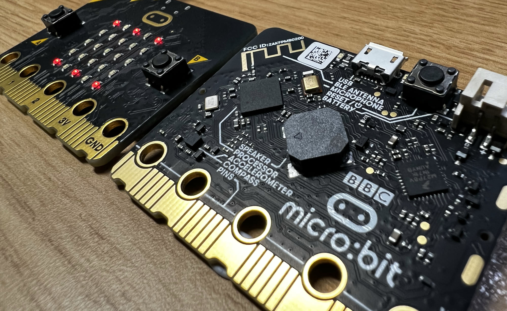
Microbit Hardware Problems and Solutions
These are a list of hardware related problems and solutions for the micro:bit v2.0 and above.
Introduction
This course uses a mix of the micro:bit v2.0 and v2.2, as the v1.x uses a different CPU and is thus incompatible with the course material. If your problem is related to the software environment/toolchain, visit the software setup page.
micro:bit doesn’t connect as a USB device/no orange LED indicator activity
Did your microbit disconnect from your machine after uploading some code, and now no longer appears as a USB device on your computer, and the yellow activity indicator LED doesn’t turn on?
This can happen if you upload malformed/buggy/nefarious code to the micro:bit that modifies particular GPIO pins that you shouldn’t be modifying. Particularly, the pins known to cause this problem if modified are in GPIO port 0, and exist within the pin range 15-28. Please check your code to make sure you haven’t accidentally modified pins you are not supposed to modify. You should only ever interact with the pins of the GPIO peripherals you are trying to use. Once you have identified and corrected the bug in your code, we can reset your micro:bit to allow you to upload the corrected code.
Solution Instructions
Make sure you have read the above section before continuing with this section.
Steps:
- Step 0: Download the two
.hexfiles in this Gitlab repository.- Instructions on how to download those files are provided within.
- The linked repository contains instructions on how to use the provided
.hexfiles to fix this problem, but instructions will be provided here too.
-
Step 1: Unplug the micro:bit, then, while holding the RESET button, plug it back in to enter MAINTENANCE mode. (You should see a ‘MAINTENANCE’ USB device appear.)
-
Step 2: Drag the
kl27z_microbit_if_crc-erase_target.hexfile into the MAINTENANCE drive. You should see the activity via the yellow activity indicator LED on the microbit, then the device should disconnect and reconnect. You should see the microbit simply alternate between flashing the red and yellow LEDs. -
Step 3: Unplug and reconnect the microbit whilst holding the RESET button to enter MAINTENANCE mode again. Now drag the
0255_kl27z_microbit_0x8000.hexfile into the drive to reflash the complete interface firmware back onto the microbit. - Step 4: Profit! The microbit should disconnect and reconnect as MICROBIT, the indication that the interface + target MCU are now working in harmony correctly again!